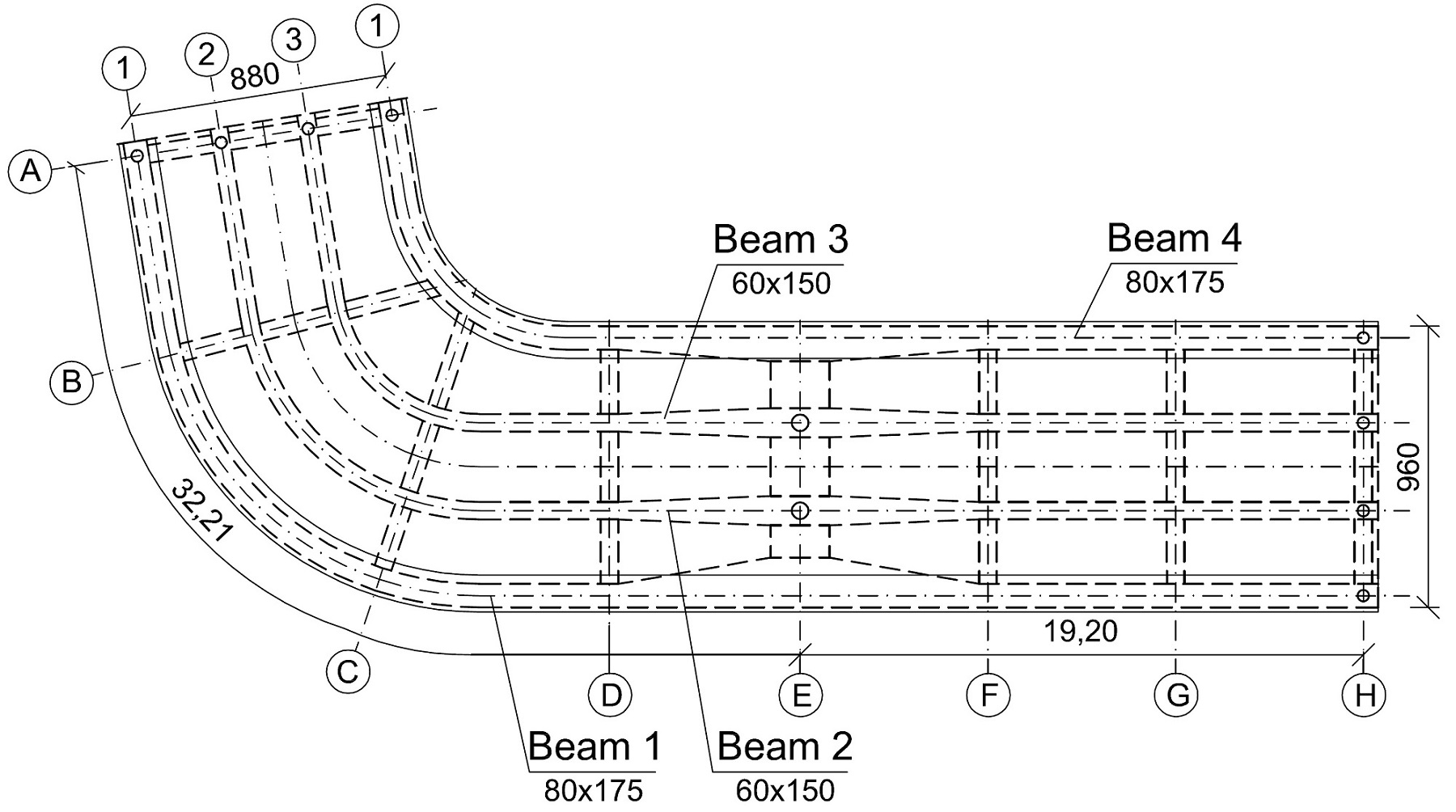
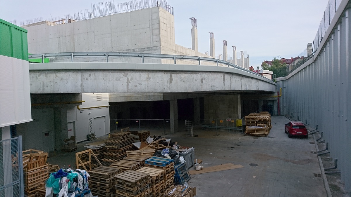
A reinforced concrete ramp has been designed in the building of shopping mall, which is being erected thiss year in Wieliczka. A ramp leads to the car park on the roof. The structure is a two-span structure consisting of 4 main beams connected by crossbars and a monolithic slab. The outer beams have a cross-section of 80 × 175 cm and the middle beams 60 × 150 cm. The slab is 30 cm thick. The structure is supported on 3 supports in the A, E and H axes. Podpora wewnętrzna w osi E to żelbetowy filar, na którym na łożyskach mostowych wsparto tylko belki wewnętrzne. Internal support in the E axis it is a reinforced concrete pillar, on which only the internal beams rest on the bridge bearings. The beams are connected with cross members with a section of 60 × 155 cm. One of the spans (between the E and H axes) runs rectilinear, and the other (between the A and E axes) runs along an arc. The angle of curvature of the arch is 81 ° and the span of the longest external beam, measured along its axis, is as much as 32.2 m. The structure is made of C35/45 concrete.
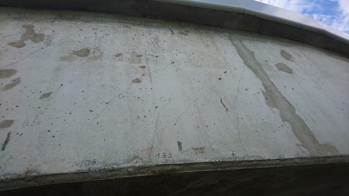
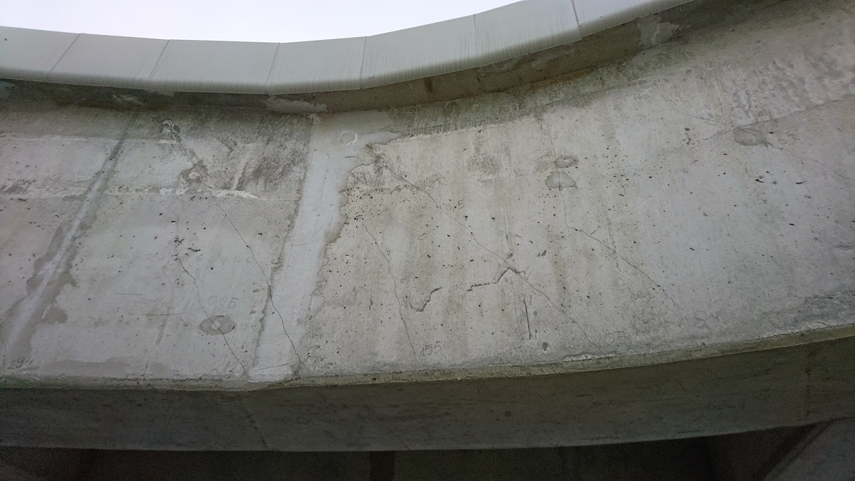
The reason why the problem came to us for analysis was excessive deflection. About half a year from the execution of the arches the span showed a noticeable deflection which gradually increased over time. During talks with the investor span was already bent about 7 cm from the chord. The arrangement of scratches with a width of up to 1.0 mm was also disturbing. On the road, in the place of the most strongly deflected external arch beam, a trough has formed. We undertook the task of examining the structure, finding the causes of deflections and proposing a reinforcemeent that could restore the safe serviceability of the structure, in such a way as not to introduce additional supports.

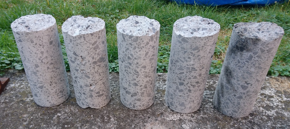
In order to determine the reasons for the failure, we performed the following work: analysis of project documentation, cracks inventory, analysis of periodically conducted geodetic deflection measurements, determination of the compressive strength of concrete on 5 cylindrical samples taken, computational analysis taking into account rheological phenomena and concrete cracking.
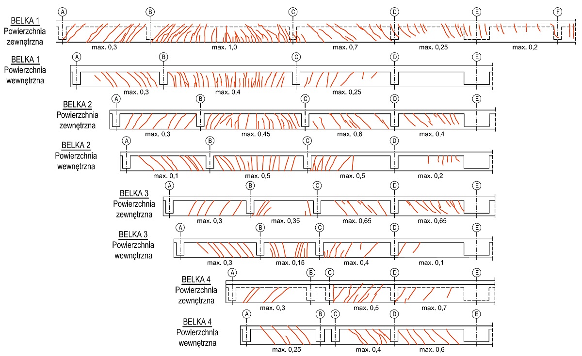
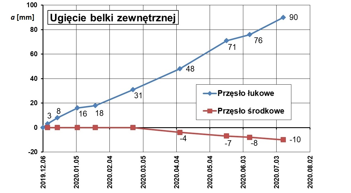

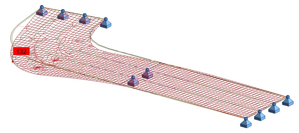
Our research showed that there were no execution errors. The layout of the scratches shown in the figure above (rysy w dówch przecinających sie kierunkach na obu powierzchniach belki) indicates, that they were formed as a result of torsion. Despite the very strong bending reinforcement (16⌀32 mm bars were used at the bottom of the outermost B-1 beam) and shear reinforcement (6 cut stirrups ⌀16 mm in spacing 15 cm) torsion cracks with a width of up to 1.0 mm. As a result of the reduction of stiffness by cracking, there was excessive deflection and increased creep of strongly compressed concrete led to a significant increase in deflections over time. Our calculation shown that long-time deflecion will up to 132 mm. Taking into account that in time of preparing the expertise deflection was 90 mm and the growth was lasting steadily (picture above) we could expect that long-time deflection will be much bigger that conducted calculations shown. Analysis of deflection even by using advaced computional methods is very hard and usually is much more different from real time-long deflection. The modeling of deflection requires of assuming difficult to expect features of concrete.
We identified a design error as the direct cause of the failure. Each building material has its limit span, above which, for a given cross-section height, he won't even carry his weight. This is a special feature of reinforced concrete, a material with a very high weight-to-strength ratio. In this case, this limit was greatly exceeded. Under the weight own structure (in this case the weight of layers and equipment is negligible compared to the weight of the structure), excessive cracks and deflections appeared. The structure did not even safely carry its own weight. Reinforcement turned out to be too heavy here. The structure should be designed as prestressed or composite (steel and concrete).
Such a significant deflection cannot be easily fixed when the deflections are caused by rheological phenomena in the concrete. You can only stop the growth of deflection and restore its serviceabilities. For this purpose, we proposed external prestressing in the form of six 12L15.5 cables. We proposed a steel deviators that give the cables the appropriate layout. Fixing the anchoring plates to the side of the structure turned out to be a big challenge. The anchor block must transfer a force of 7200 kN to the concrete. This fastening is to be realized by means of 35 M42 anchors glued into the concrete.
a
© Designed and coded by ![]()